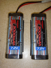
We have a brand new robot for February. We modified a 12-volt conversion that we've been working on for a few years. It begins with two 7.2-volt batteries that are wired in series.
|
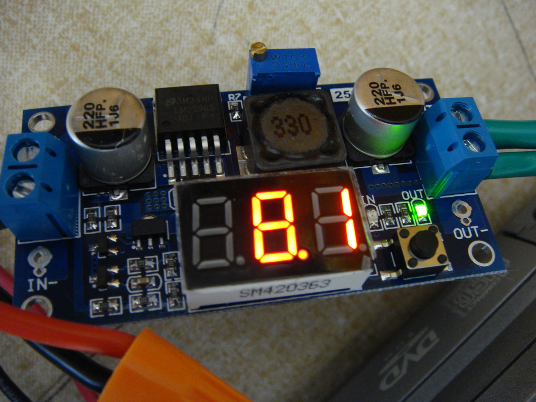
Approximately 14.4 volts flows into the buck convertor, and it drops the voltage to approximately 8.1 volts so it can safely enter the micro-controller.
|
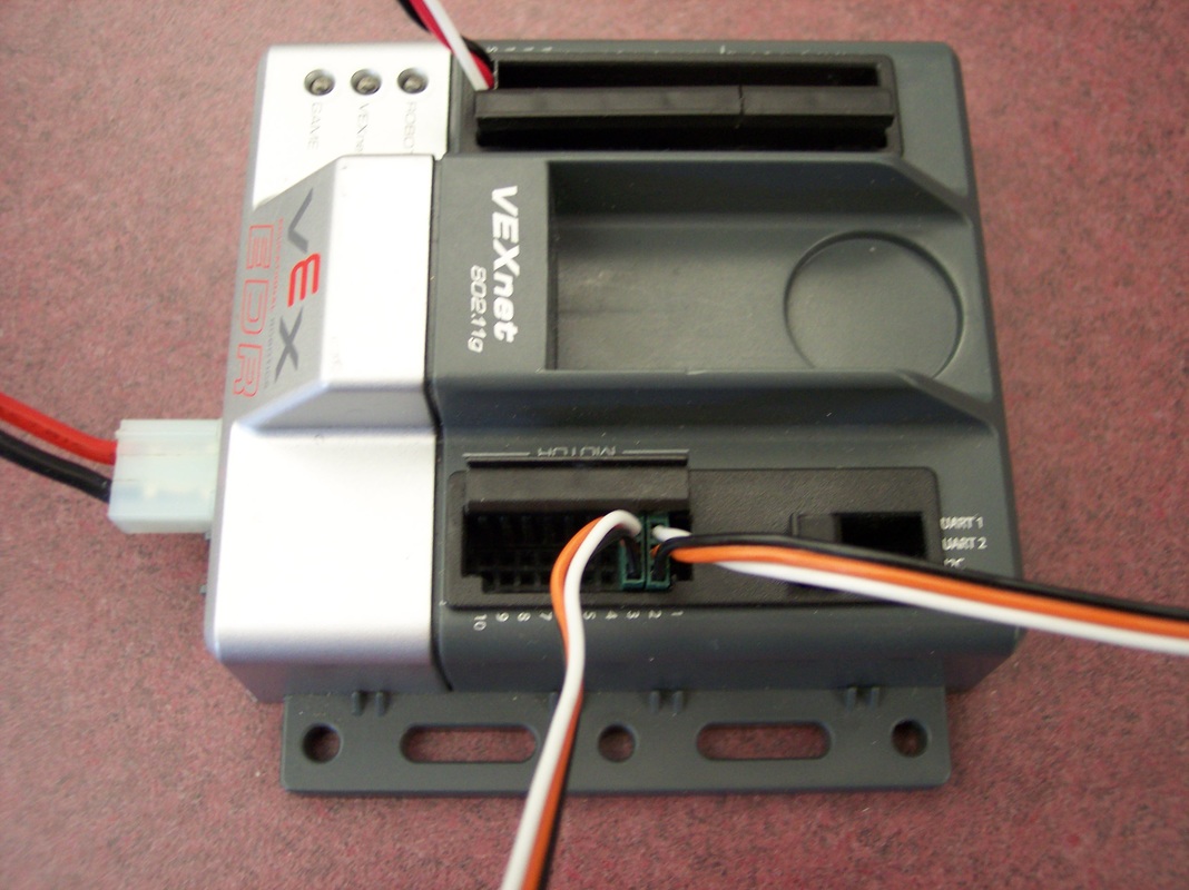
The voltage flows from the buck convertor into the micro-controller, which sends PWM signals to the speed motor controllers.
|
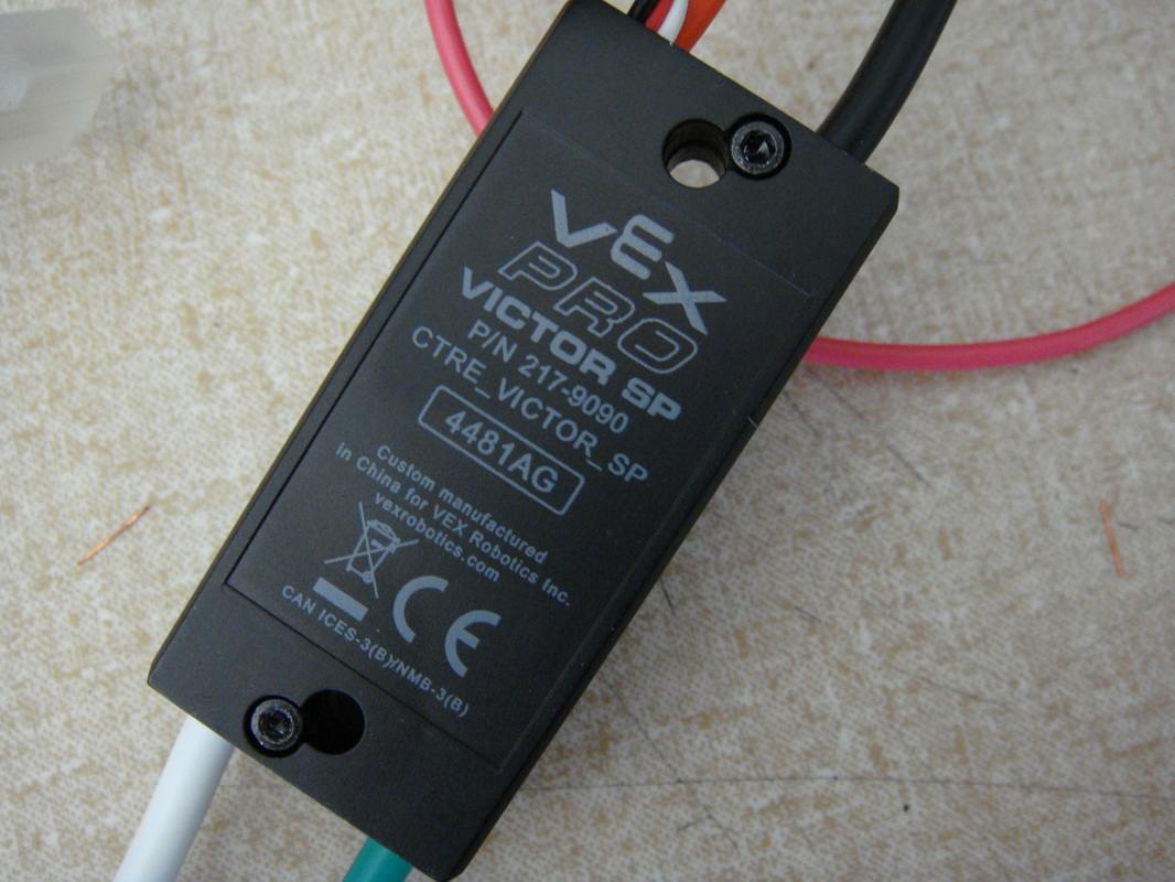
Prior to entering the buck convertor, wires will be diverted to power the motor speed controllers and the 12-volt motors. The motor speed controllers receive PWM signals from the micro-controller to control the voltage of the motors.
|
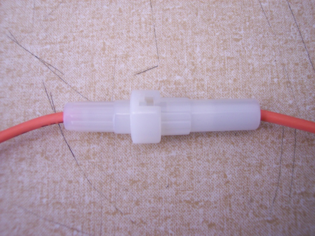
On its way to to 12-volt motor, the power flows through a 20-amp fuse--just in case. We do not want to burn out our motors.
|
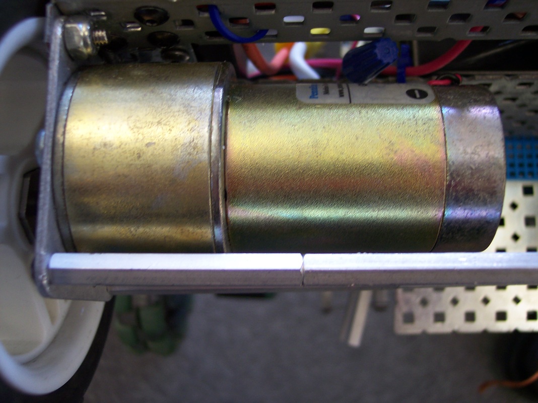
Our motors are salvaged Pittman 19:7:1 12-volt motors.
|
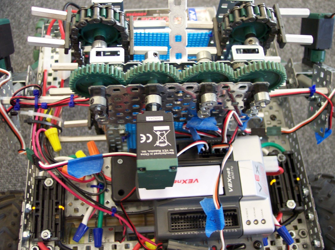
This mess is our 12-volt conversion system as squeezed onto our robot. The black boxes on the left and right are the motor controllers. The black box in the center under the micro-controller is the buck converter.
|
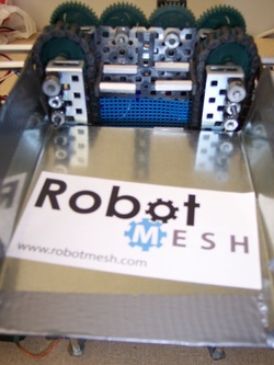
The rear of the robot in non-extended mode shows our omni-wheels, in-take rollers, and ramp.
|
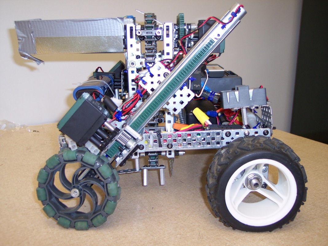
The right side of the robot shows a slider that extends one of the rear omni-wheels. You can also clearly see the center stand-offs that are used to carry the protons up the proton lifter.
|
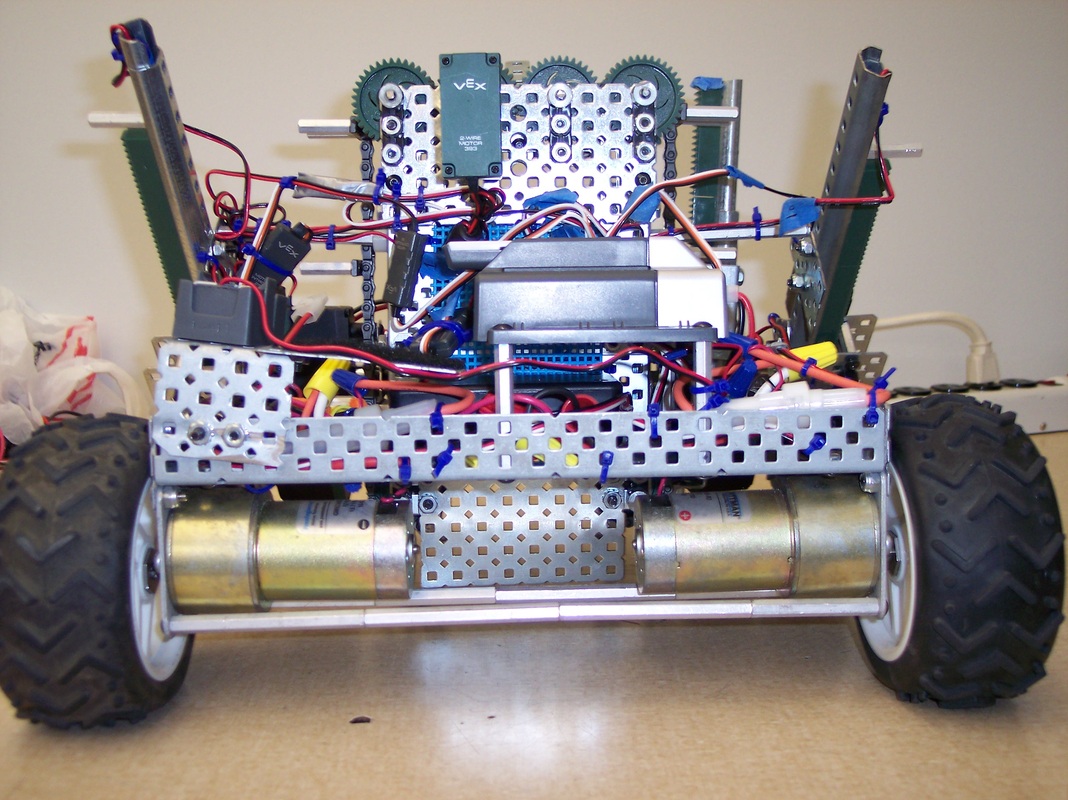
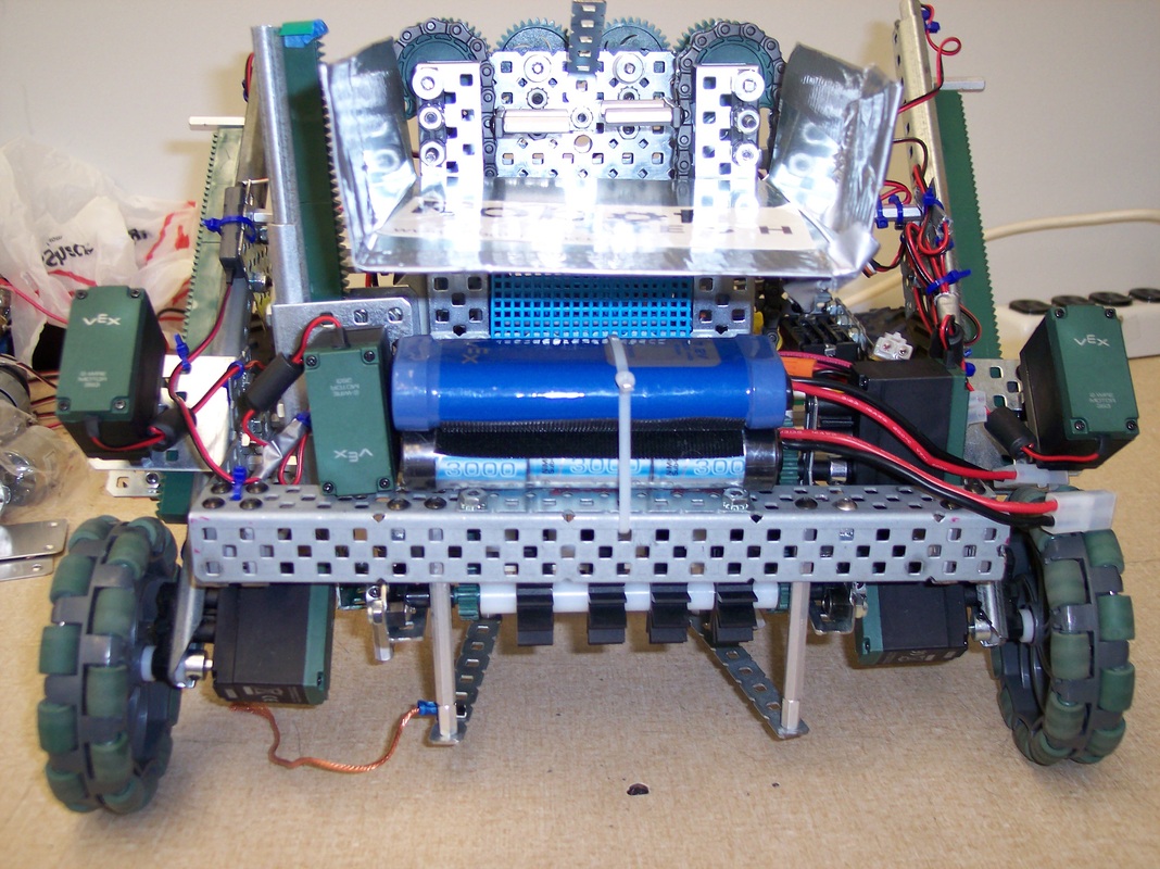
The front of the robot carries the essentials for the robot: the micro-controller, speed controllers, batteries, fuses, and the buck convertor.
|
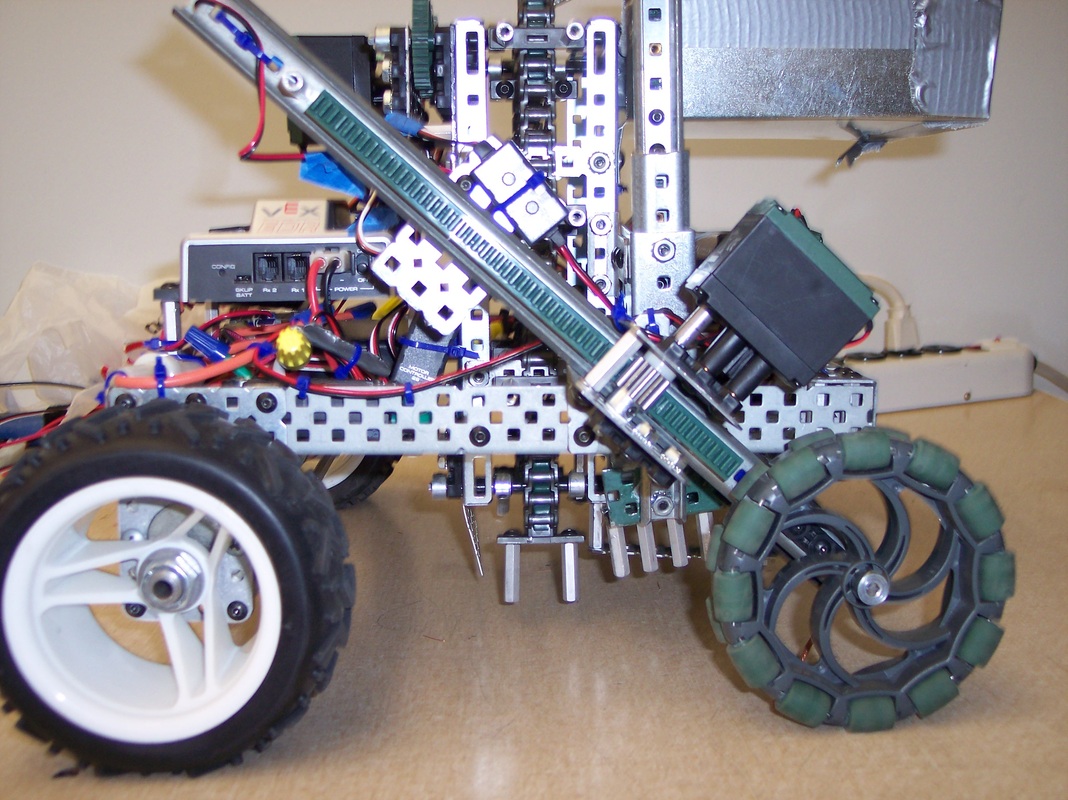
The left side of the robot shows the slider that extends the other omni-wheel and the intricate mess of wires that is the 12-volt conversion set-up.
|
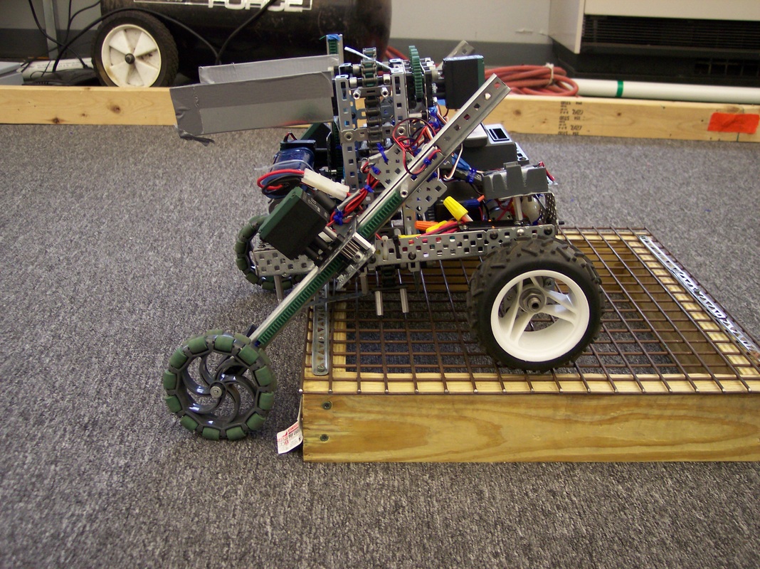
The larger rubber wheels are used to drive onto the crossover platform.
|
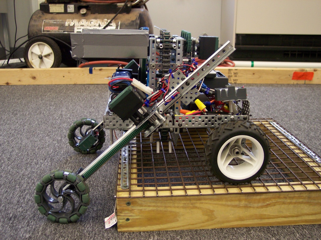
The back sliders (aka the extenders) are used to keep the body of the robot parallel to the platform.
|
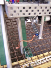
A fork can be driven down between the holes of the grate to prevent removal from the crossover platform and to aid in lifting the wheels from the carpet.
|
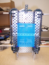
This is the proton lifter before it is installed on the chassis.
|
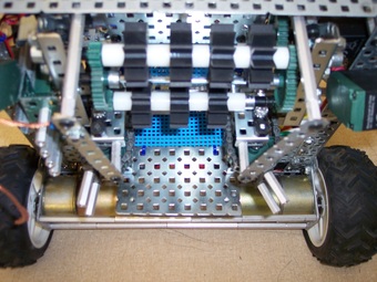
This slightly raised view shows the two rows of intake rollers and the entrance to the proton lifter.
|
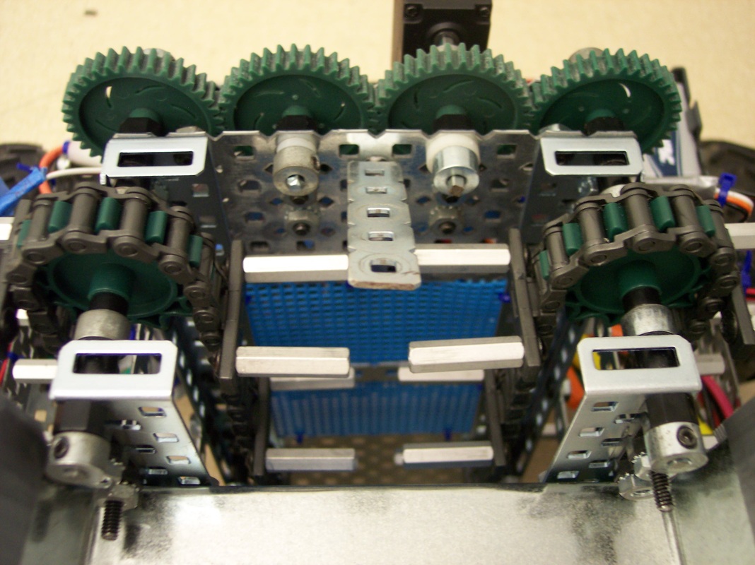
Notice the piece of metal that is bent forward in the upper middle portion of the picture. This piece forces the proton forward and away from the proton lifter toward the chute.
|
The chute allows the robot to use gravity to quickly drop the proton back through the booster.
|
